Loading bays fitted with high-visibility yellow wheel guides
Loading Bay Safety

Guide Every Vehicle.
Secure Every Loading Cycle.

Straight and cranked wheel guides improve vehicle alignment. Automated Rite-Hite wheel restraints add controlled trailer engagement, interlocks and clear traffic-light communication.

3Typical guide lengths
UKSurvey and installation
1Integrated bay system
Two Different Functions

Alignment and restraint are not the same thing.

Wheel guides help a driver reverse squarely towards the loading bay, reducing the chance of poor positioning and contact with nearby equipment. A vehicle restraint is a separate safety system designed to help prevent unintended trailer movement during loading.

EVICK can survey the complete bay and specify guides, restraint, controls, warning lights and interlocks as one coordinated solution.

Wheel Guide Options

Straight or cranked: which profile fits?

The best arrangement depends on the approach, vehicle mix, available yard space and condition of the concrete.

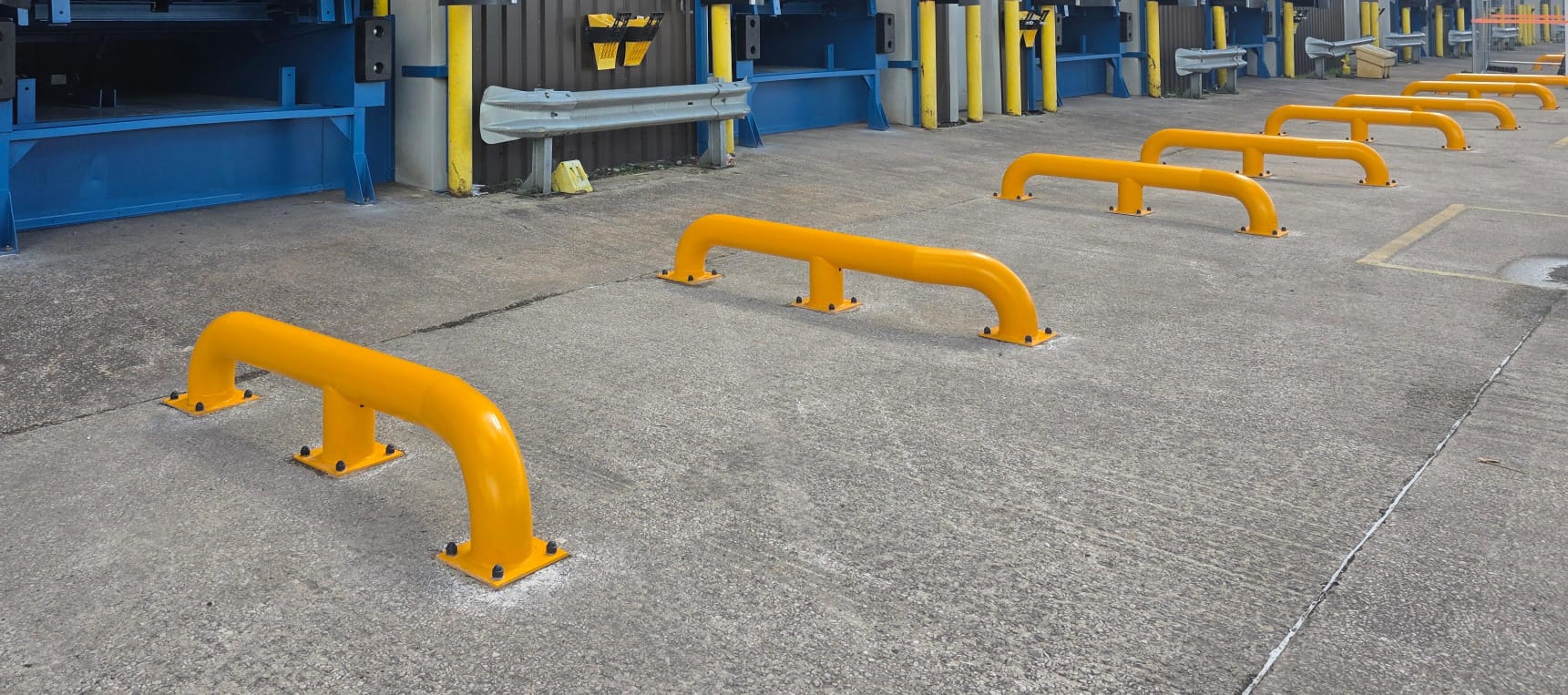
Short straight wheel guides installed in front of loading bays
01

Straight Wheel Guides

A parallel guide provides a robust, clearly defined route towards the bay. It is well suited to controlled approaches where vehicles are already reasonably square.

  • Simple, durable construction
  • Useful where approach space is controlled
  • Helps maintain alignment close to the bay
  • Available in different lengths to suit the site
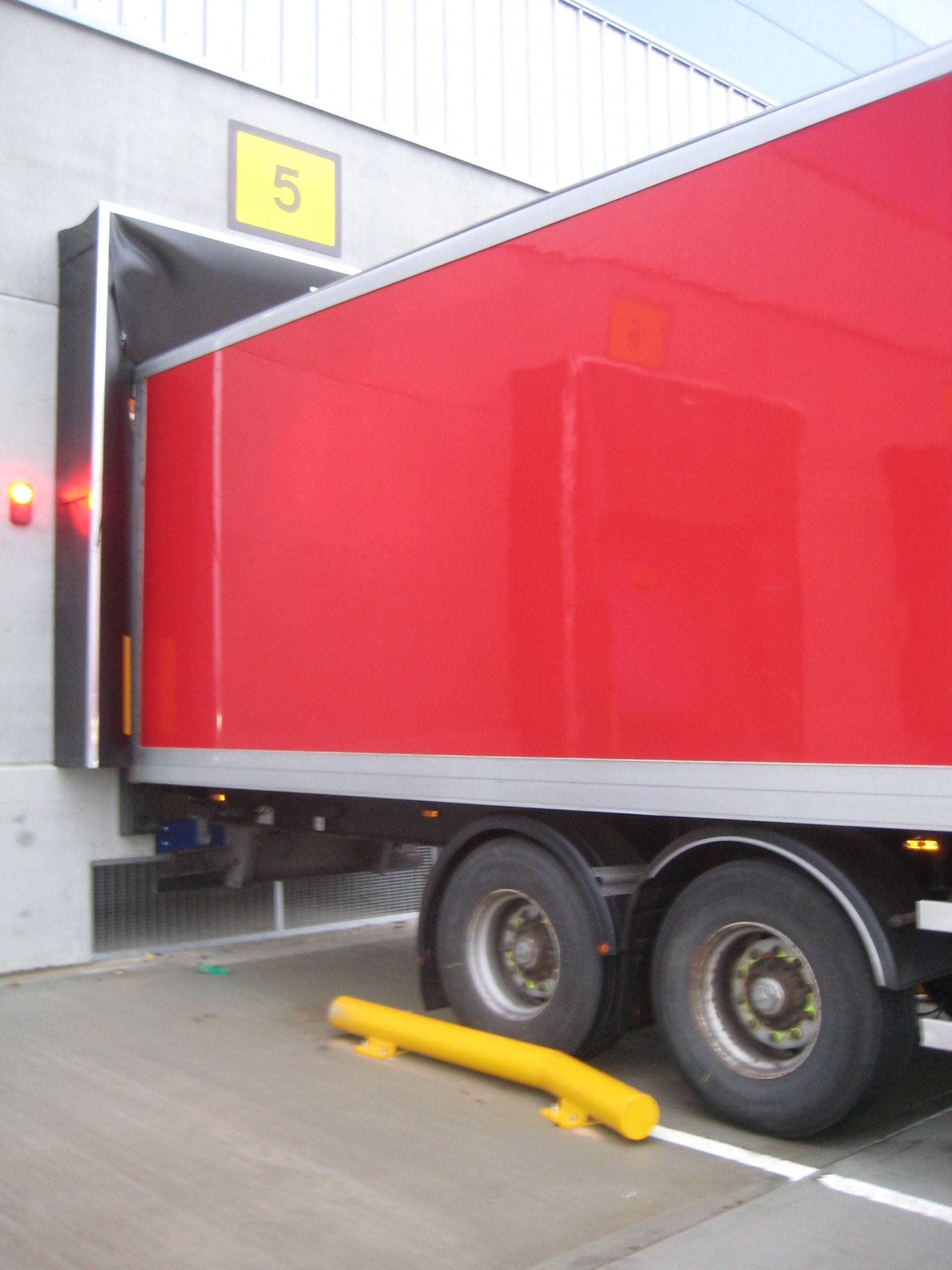
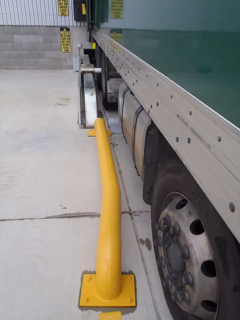
Lorry reversing alongside a flared wheel guide
02

Cranked or Bent Wheel Guides

The flared entry creates a wider target before guiding the vehicle into its final position. This can be more forgiving where approach angles and driver positioning vary.

  • Funnel-shaped entry assists initial alignment
  • Useful on busy or less direct approaches
  • Helps guide trailers towards the bay centreline
  • Can reduce repeated shunting when correctly specified

Important: wheel guides assist alignment only. They do not restrain a vehicle and do not replace an appropriate restraint, chocking system or safe loading procedure.

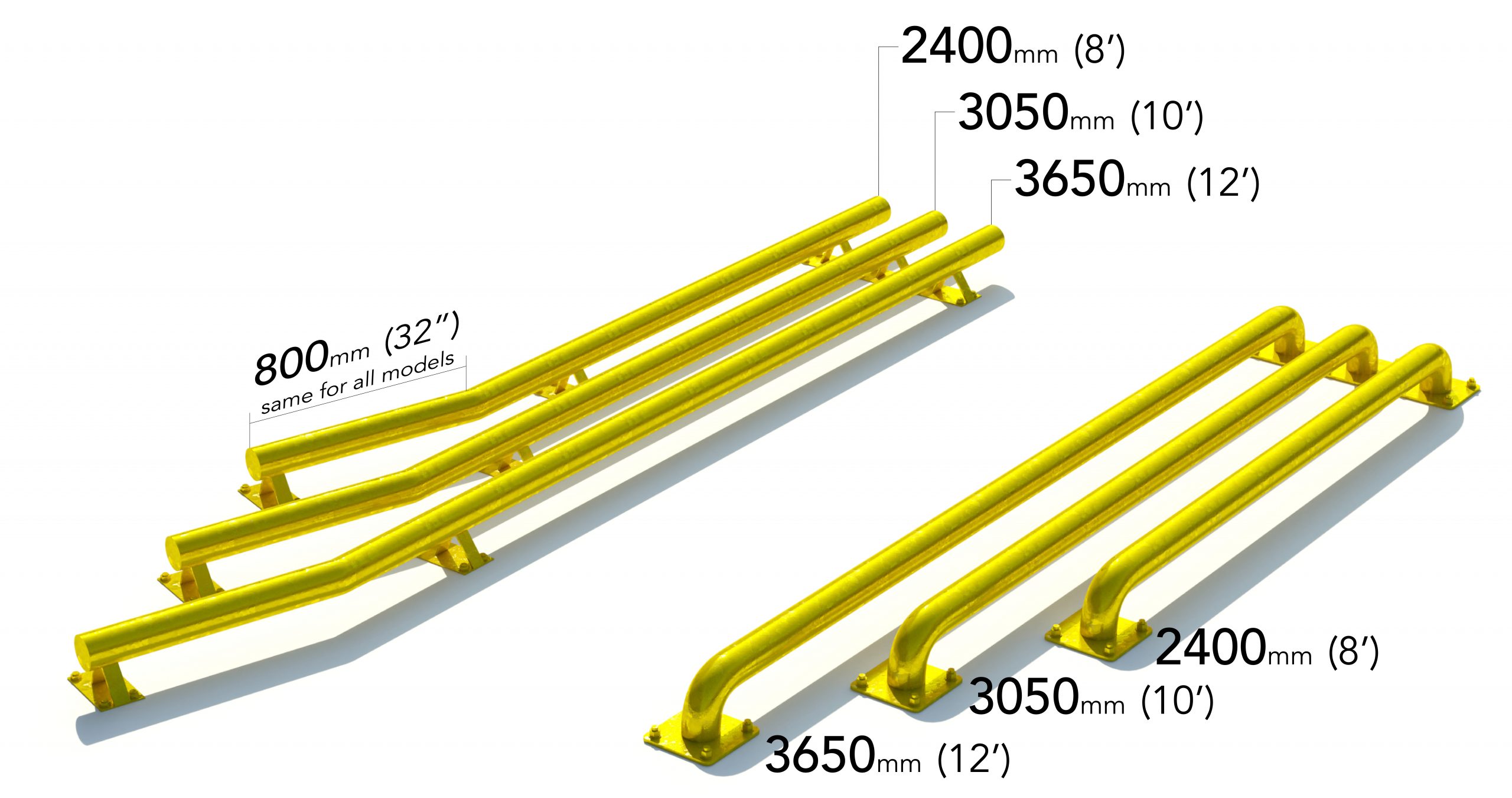
Illustration comparing straight and bent wheel guides in several lengths
Length Selection

More guidance where the approach needs it.

The illustrated range shows typical 2400 mm, 3050 mm and 3650 mm guide lengths. Final dimensions, tube size, supports and fixings must be selected after a site survey.

2400 mm / 8 ftCompact guidance for controlled approaches and restricted space.
3050 mm / 10 ftA versatile general-purpose length for many loading yards.
3650 mm / 12 ftA longer alignment path for busy bays or less forgiving approaches.

Illustrated sizes are examples, not a specification. Concrete condition, fixings, drainage, impact risk and vehicle swept paths all require assessment.

Automated Vehicle Restraints

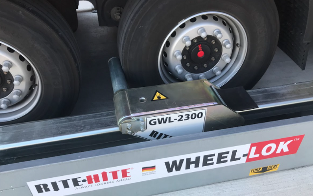
Rite-Hite Wheel-Lok: positive wheel engagement.

For loading operations that need more than visual guidance, a powered wheel-based restraint can help secure a suitable trailer at the bay and communicate its status to people inside and outside.

Rite-Hite Global Wheel-Lok positioned against a trailer wheel Wheel restraint installed alongside a loading-bay wheel guide

Wheel-based restraint

Engages a suitable trailer wheel rather than relying on a rear impact guard, making it relevant to a broad mix of trailer arrangements.

Automatic positioning

The selected Rite-Hite system can automatically locate and secure the wheel within its operating range, subject to vehicle and site suitability.

Clear status indication

Internal and external lights tell warehouse staff and the driver whether the bay is in a secured loading state or released for departure.

Interlocked operation

Controls can be configured so the restraint, loading-bay door and dock leveller follow an agreed safe sequence.

Typical Operating Sequence

A controlled process from arrival to release.

  1. 01

    Vehicle arrives

    External green indicates that the driver may approach the bay.

  2. 02

    Vehicle aligned

    Wheel guides help position the trailer squarely at the loading point.

  3. 03

    Restraint engages

    The wheel restraint secures a suitable trailer wheel and confirms engagement.

  4. 04

    Loading enabled

    Internal indication confirms status; configured interlocks can permit the door and leveller sequence.

  5. 05

    Bay made safe

    After loading, the leveller and door return to their safe stored positions.

  6. 06

    Vehicle released

    The restraint disengages and external indication changes to permit departure.

This is a typical example. The exact light logic and operating sequence must be agreed during design, risk assessment and commissioning.

Integrated Bay Controls

One sequence. Fewer opportunities for error.

Where suitable, EVICK can coordinate the vehicle restraint with other loading-bay equipment. A planned sequence helps prevent the door or leveller being used before the vehicle is confirmed in the intended state.

  • Internal red/green operator indication
  • External red/green driver traffic lights
  • Audible and visual warning options
  • Door and dock-leveller interlocks
  • Fault indication and controlled overrides
  • Operator training and handover
External redVehicle remains at the bay
Wheel secured
Door and leveller enabled
External greenVehicle may depart
Site Survey

Specified around your vehicles, yard and working method.

A restraint system is only effective when it suits the vehicles and the complete loading operation.

Vehicle mix

Trailer types, wheel positions, liftgates and operating variations.

Approach geometry

Yard space, reversing angle, bay spacing and vehicle swept paths.

Foundations

Concrete condition, drainage, levels and suitable fixing locations.

Existing equipment

Doors, levellers, controls, power supplies and communication devices.

Site procedure

Loading sequence, responsibilities, exceptions and emergency arrangements.

Future support

Planned maintenance, testing, repairs and operator refresher support.

Common Questions

Wheel guide and restraint FAQs.

Are bent wheel guides always better than straight guides?

No. A flared guide can help capture vehicles approaching at a wider angle, while a straight guide may be more suitable for a controlled approach or restricted yard. The correct choice follows a site survey.

Can wheel guides stop a trailer moving?

No. Their purpose is vehicle alignment. They are not a wheel restraint and should not be treated as a replacement for an appropriate restraint or chocking procedure.

Will a Rite-Hite wheel restraint suit every vehicle?

No single system should be assumed suitable for every vehicle. Trailer geometry, wheel position, liftgates, ground conditions and the operating range must be reviewed before selection.

Can the restraint be linked to our dock door and leveller?

Yes, compatible equipment can be configured with sequential interlocks and status signals. The exact arrangement depends on the existing controls and agreed operating philosophy.

Do these systems require maintenance?

Yes. Wheel restraints, lights, sensors, controls and mechanical components should be inspected and maintained at an appropriate frequency for their use and environment.

Plan a Safer Loading Bay

Let EVICK survey the complete vehicle approach and loading sequence.

We can advise on guide profile and length, restraint suitability, traffic lights, interlocks, installation and ongoing support.